

Fuses for DC voltages
DC and PV – DC-voltage fuses and Photovoltaic fuses
Introduction
We know fuses and "fuses". The consequence of using a incorrect electric fuse in an incorrect electric circuit can cause its explosion and/or the destruction of neighbouring appliances. Greater consequences can occur in the case of destruction of protected appliance –transformer, inverter or the damaging of electrical installation. In the article we will present the problem of activity of fuses in DC electrical circuits as well as several examples of usage of
fuses in photovoltaic systems connected to the public grid.
| Viktor Martinčič Product manager for fuse systems, Chair of IEC technical committee for fuses TC 32 |
Why should we use a fuse at all?
A fuse is only one of many devices in electrical installation which are as a "sacrificed" element incorporated in the electric circuit. Fuses are designed in such a way so that they can interrupt electric circuit if excessive electric current appears in it. This can occur because of overloading or any other defect. In this way, with the interruption of the circuit further injuries of other elements of the circuit which could occur if the protecting device would not be included / comprised – in this case the fuse. As it has already been mentioned, the fuse is in a way sacrificed because it is destroyed and it has to be
replaced.
The properly chosen fuse can prevent fire or the remaining damage when the connection cable contacting unpredictably impairs (for example in electric circuit photovoltaic module - inverter), if the connection cable distribution board suddenly comes in a contact with earth terminal, if it comes to the short circuit because of the fallen screw or/and if the destruction of isolation and consequently short circuit are caused by animals.
It is generally known that in the case of long-continued overloading or short circuit caused in any kind of way the melting element inside the fuse blows out. At the same time, if the connection cable is correctly calculated (its ampacity has to be higher than the nominal fuse current), the fuse will operate in time and in this way it will prevent the isolation from burning and further damage.
Categorization of fuses
The fuses are categorized according to the rated current, nominal voltage, rated breaking capacity and also if they are appropriate for usage in electric circuits with alternate current (a.c.) or direct current (d.c.).
Rated (nominal) current of the fuse is the value of the current which can carry continuously without deterioration under specified conditions.
Rated (nominal) voltage is the value of the voltage with which the fuse can extinguish the existing arc without influencing the surroundings.
Rated breaking capacity is a value of prospective current that a fuse is capable of breaking at a stated voltage under the prescribed conditions of use and behaviour.
Are AC and DC fuses the same?
No, they are not. Theirs fusible elements, as most important parts of each fuse are differrent. When we compare the ability of interrupting AC and DC currents we should be aware that at AC conditions the value of the current is more ten times in a second crossing through zero value and here is the ability to extinguish the electric arc made easier.
The interruption of the DC current occurs much difficulty and the reason for that is that short-circuit current flows only in one direction up to arc extinguishing is achieved.
The melting element in DC fuses has to be designed in order to interrupt the current in the electric circuit with the “sufficient power” if too high current flowing too long. This should occur inthe shortest time possible in order to extinguish the electric arc that occurs at that moment.
DC fuse-links are relatively complexed elements which contain a great deal of interacting particularities. Because of that the price of DC fuse-link is slightly higher that ordinary links. Some of fuse-links are marked as AC and as well with DC permissible value of nominal voltage.
Low voltage fuses (fuses used mainly for industrial use, see standard IEC 60269-2, Ed.3, 11/2006) have minimum defined breaking capacity 50kA a.c. and 25kA d.c.
Breaking capacity of the fuses in electric circuit with greater time constant (where great d.c. motors are used for instance) should be appropriately adapted – derated. Of course it is also affective the other way round - in networks in which great inductivity is not expected, such as in battery power feeders, we can also expect greater breaking capacity as nominal.
The breaking capacity of the fuse-link has to be looked upon from the viewpoint of time constant which applies to the electric circuit discussed at the moment.
More detailed information are generally supplied by the fuse-links manufacturer’s or they can be defined and proved by testing. It depends on the manufacturer whether it tests its products only on AC voltages (which is usual) or also on DC.
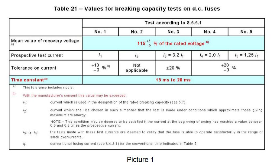
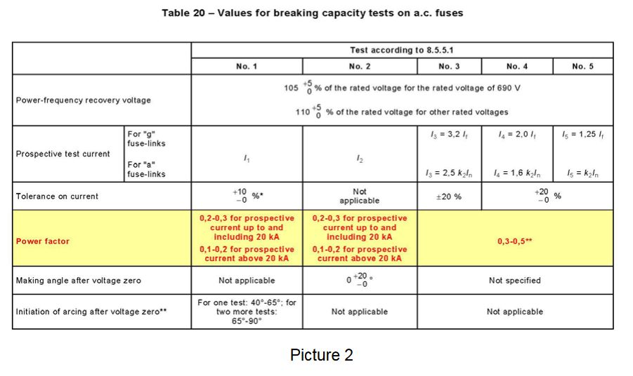
On the pictures 1. and 2. tables of standard tests for NH fuse-links are presented, separately for DC and AC voltage (see IEC 60269-2) In the table on the first picture additional requirementsfor the value of time constant (inductivity) of DC electric circuit is given. The value has to be between 15 and 20 ms.
What is influence of the time constant on the electric circuit?
In practice protective device, such as circuit breakers or fuse-links, can work irregularly if the time constant (industiviry) of the electric circuit is too high. In other words, the protective appliance can not extinguish the arc… !
The time constants that are too high can be very inconvenient for the accurate operation of the protective devices. Problems can also occur at lower voltages as nominal and short-circuit currents that are smaller than nominal breaking capacity of the protective appliance.
As the length of the connection cable grows the resistance of the electric circuit also increases. As the distance between parallel connection cable (positive and negative pole) grows, the inductivity grows as well. Similarly, it also occurs with capacitivity but its value does not flow uniform.
The three factors mentioned (resistance - R, inductivity - L, capacity - C) determine the time constant T of the electric circuit which is expressed in units ms (millisecond). We have to pay special attention to the method of practical assembling of all the elements in the electric circuit.
Are DC fuses useful also in the field of renewable energy sources?
Yes, it is one of the most developing areas and one of the most important areas of electrical energy production is undoubtedly solar (photovoltaic PV) energy production. Electrical energy is produced in Solar plants, where a semiconductor solar cells convert sun light directly into
electrical energy.
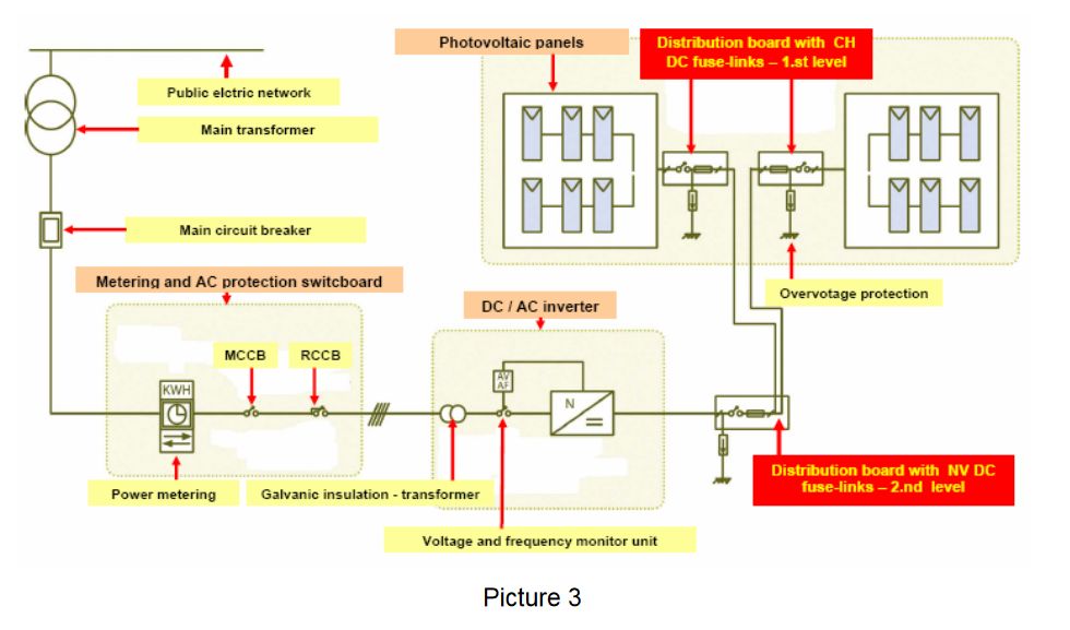
The electrical installation drawing (scheme) of the standard photovoltaic system which is connected to the fixed electric power network is shown on the picture 3. In the continuation the elements of the photovoltaic systems will be defined as PV (from the word Photo Voltaic), so PV fuses, PV modules, PV system, etc.
The usage of fuses in PV systems is different. It mostly depends on the regulations and technical practice of individual state. In USA, Canada and Mexico they mostly stick to document- regulation titled »Photovoltaic Power Systems – Suggested practices« when designing PV systems. The document was prepared by NEC (National Electrical Code).
It is OBLIGATORY to use PV fuses in all PV systems that are connected to the public electric power network. The situation in Europe is rather different.
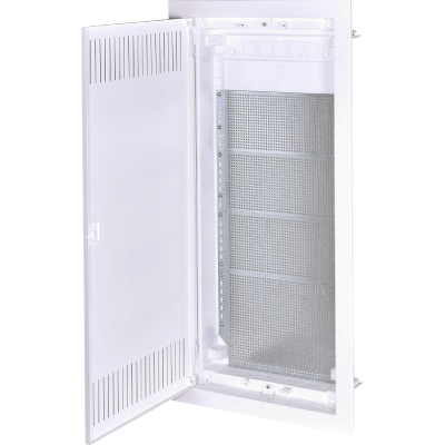
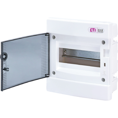
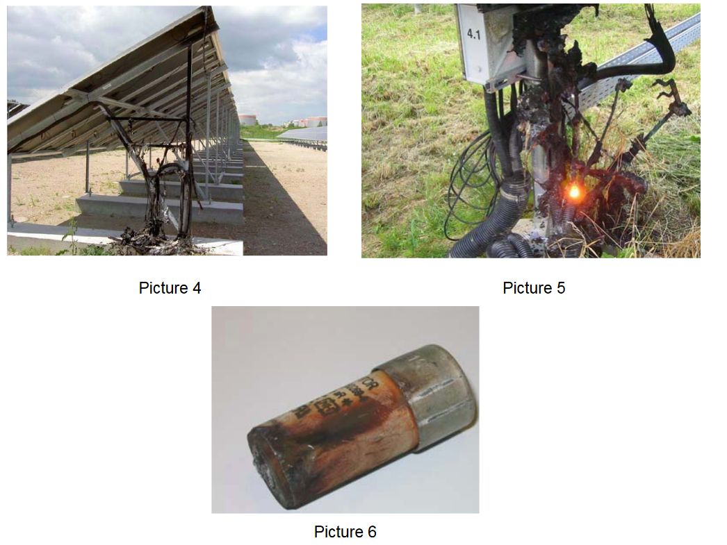
While in Germany people are quite skeptical when it comes to using special fuses for PV systems, the situation in Spain and Italy is rather different. After having problems which occurred in the past (the destruction of the installation and distribution box – look the following pictures no. 4. and 5. and 6.), they decided that the use of fuse-links is OBLIGATORY.
Before we will continue with the description of short-circuit protection of PV systems we shall shortly describe the function of of solar installation components.
To produce electrical voltage (energy) from the sun’s energy we use semiconductor (mono- crystal or poly-crystal) silicon’s solar cells, which generate the electrical voltage if they are exposed to sunlight.
The solar cells of the size 12,5 x 12,5 cm generate with approximately from 0.6V voltage and up to to 3,5A electric current. To achieve higher voltage we should connect solar cells in serial connection. Such connected solar cells are named “PV modules” see picture 7.

They are already composed at the manufacturer’s of PV modules where several modules are electrically connected and they reach the surface from 1,5 to 2,5 m². Such a module generatesfrom 30V to 60V DC voltage.
The achieved voltage of one module is approximately 30V d.c. This voltage is constant and is changed only in case when sunlight does not reach PV module. Module also generates output current which values are from 4A to 7A, depends from the type of the PV module. For achieving higher currents, PV modules should be connected in parallell –we get »strings« and gained outout currents in the rank from 25A to 35A.
This current is then connected to the »DC/AC inverter«. It is electronic device which convert DCcurrents (voltage) to AC current (voltage) – see picture 4. AC current/voltage is transmitted into the public electro energetic network over remaining elements – galvanic isolated transformer, electrical metering system and main circuit breaker.
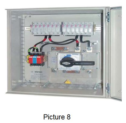
In the picture no. 3 it is shown that more modules are connected in the series. Example of PV distribution box is presented on the picture 8.
An example of two levels of protection in PV systems:
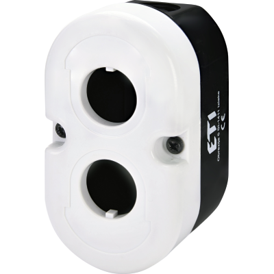
1 st The level of protection is used specially for disconnection of DC short circuits in the area of panels – right next to the solar fuse-links (further on CH10 gPV) placed into cylindrical disconnector type PCF DC (see picture 9).
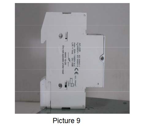
The first level enables physical and electrical separation of each individual panel. It is important to emphasize that the discoonnector is placed on the positive and as well as on the negative pole. Our example on the picture number 9, seven modules are connected into the panel. For their short circuit protection is necessary to have 14 PCF DC disconnectors where suitable CH 10 DC fuse-links with gPV characreristic are placed.
2 nd The level of protective fuse-links is usually located near the entry of the invertor’s connection and is electrically connected with the cylindrical disconnectors from the first level. The fuse-links, usually NV DC with nominal DC voltage 750V or higher are placed near the NH disconnector which enables safe and quick electrical separation of the invertor and the entire unidirectional part with PV panels.
On this level NV DC fuse-links with DC voltage 750V up to 1.100V d.c. are used. They are also in the production range of ETI d.d. The introduced example is, of course, not the only one, others will be described in the future articles.
Sources:
- NEC »Photovoltaic Power Systems – Suggested practices«
- Internal ETI reports and knowledge
- Code Corner – Photovoltaic Systems Assistance Center, Sandia National Laboratorie